
Published August 19, 2026 · Updated August 19, 2026
How to Measure Conveyor Idlers and Pulleys for Replacement
A clear measurement sheet and photos reduce the chance that a replacement component fits one dimension and misses the frame, bearing, shaft, or duty.
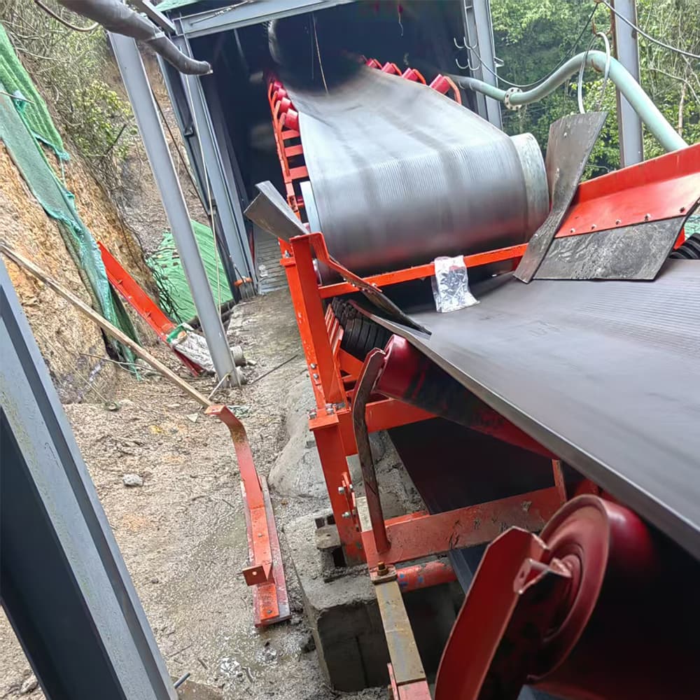
Conveyor rollers prepared for replacement measurement and matching
/images/conveyor-idlers.jpg
Measure the complete idler interface
- Tube diameter and wall thickness where known
- Roller face length and overall length
- Shaft diameter, end shape, flats, slots, holes, and threads
- Bearing code, seal arrangement, and lubrication
- Frame spacing, trough angle, belt width, and idler position
- Belt speed, spacing, load, impact, dust, water, and corrosion
Record pulley geometry and operating load
- Pulley function: drive, tail, bend, take-up, snub, or wing
- Shell diameter, face width, and lagging type and thickness
- Shaft steps, keyways, threads, and total length
- Hub or locking assembly and bearing housings
- Belt width, speed, tension, wrap angle, drive connection, and power
- Failure mode such as lagging wear, shaft crack, bearing heat, or shell damage
Use drawings, photos, and a sample together
Photograph the component in place, the mounting points, nearby frame, labels, damaged area, and a ruler against key dimensions. A current drawing or physical sample is valuable for non-standard shaft ends, hubs, and frames.
Keep a removed component until the replacement drawing is approved. It remains the most direct reference if the site records are incomplete.